Installation and Commissioning
‹ ‹ Back
All cloud electronic access control suppliers have to know the installation and commissioning process when it comes to deployment of the system. It is very important to stress on containment or protection of the cables plus the fixing to ensure their security and resistance to the elements, abuse and mechanical impact. Inspection of the equipment, parts and the software.

4 stages involved in installation process of electronic access control system.

The process includes:
01. Installation of system cabling 03. TimeTec Access Account Setup
02. Connection and testing of system components 04. System Handover - Tests required at the commissioning stage
0.1
Installation of system cabling


During installation of system cabling, there are two objectives that need to be met. First is to ensure the neatness of the finished system and second is to protect vulnerable wiring.
Installer must recognize the basic needs before proceeding with any installations of electronic access control system.


Cable must be installed within a controlled area
Cables are to be concealed
If cables are exposed to possible mechanical damage or tampering or visible in public areas, they should be protected by trunking or armor
Check release signal of an access point and if it exceeds the controlled area, use metal conduit or containment to amend it
The system must support all interconnecting wiring
Installation must conform to good working practice
Cable joints must be made appropriately i.e. wrapped, soldered, crimped, etc
Not to run low voltage and signal cables in close proximity to mains or other transient carrying cables
Low voltage cables from mains and standby power supplies to remote equipment are to be of sufficient size to permit sufficient operation of the equipment at the end of any proposed length of cable run


Cable routes
Installer needs to familiarize with the site and identify the routes used by existing cables and services. Check to see whether it may be possible to share these routes and maintain segregation from the existing cables. If it’s not possible to share the existing cables, look for new runs and establish a method of fixing the new cables so that they are not vulnerable to damage. And if there’s no way to install these cables in protected positions, use containments to hold the wiring. Running cables through voids is preferable due to cost issue than using containment.

Cable types
In access control systems, it is important to run separate cables to the different components. Certain signals can be carried within different cores in the same cable without interaction BUT data and control signals must be carried in separate cables and components. The cables types are therefore governed by a number of features including the compartment in which they are to be installed. When talking about cables, their fixing is also very important. There are a few options for fixing which include steel conduit, non-metallic conduit, trunking and flange trys, aluminum tubing and capping/channeling.

Underground cabling
If any underground cabling is involved, suitable ducting should be employed, which is sealed with non-combustible material after the cables have been drawn into position. For increased security of the cabling rot resistant buried cable warning tape or warning brickwork can be applied above the ductwork.

Overhead cabling
There are some circumstances where overhead cabling is required. Please make sure to follow the following guidelines when you install an overhead cabling:

Cables are to follow contours
Cables shouldn’t run closer than 10.5cm to any fixing points such as the corner of a ceiling to a wall
Cables are to be sited away from door frame uprights
All wiring should travel in straight lines
Never run cables diagonally across walls
Apply containments to cable of they are likely to suffer damage
Don’t use jacketless cables
Do not pass cables close to steam or hot water pipes
Data and communication/signaling cables should be kept isolated from mains cabling and heavy current apparatus and wiring and only cross it at right angles


Inspection and testing of the mains supply
All access control systems are permanently connected to the mains supply, although batteries may be used as a secondary supply for standby purposes. The cabling of the entire network, including the signal and data communication should be tested before connection of any equipment. However, modern cables are unlikely to break down and most faults with them occur during the installation process or causes by other building works on sites under construction.
0.2
Connection and testing of system components


Cabling
The first step is to consider the normal interface between the equipment and the wiring such as the wiring connectors, terminal blocks or the other methods by which the cables are to be terminated. Bad connections lead to high resistance and voltage drops. Be careful at these interfaces because so many problems are caused at these stages.

Equipments
Once the cabling has been terminated and proved satisfactory, it’s possible to test the equipment. All equipment should be confirmed as able to withstand air temperature o 0-40 degree C for internally sited equipment and -20 to 50 degree C for externally sited equipment. You can break down the test schedule into the following areas:

Perimeter Protection Hardware
This testing consists of hardware and locks such as closers, sensors, push-to-exit buttons and etc.
For the Perimeter Protection Hardware, 10 things you need to check for:


Correct alignment of all the hardware to ensure that they function properly
Correct operation in accordance with the specifications of the hardware
Make sure that as the lock is energized or de-energized, it performs as specified for emergency purposes
Test whether the locks failing in the correct fashion fail locked or fail unlocked
Manual overrides functioning smoothly and overcoming any electrical malfunction
Ensure that all sensors give the correct response to the door position
Check the operation of door closers to ensure they pull the door closed with the correct force
Push-to-exit buttons should be verified for operation
Perform a test to prove that timers generate alarm activation when doors are open for longer than their preset period
Prove that the door lock remains energized for the timed period
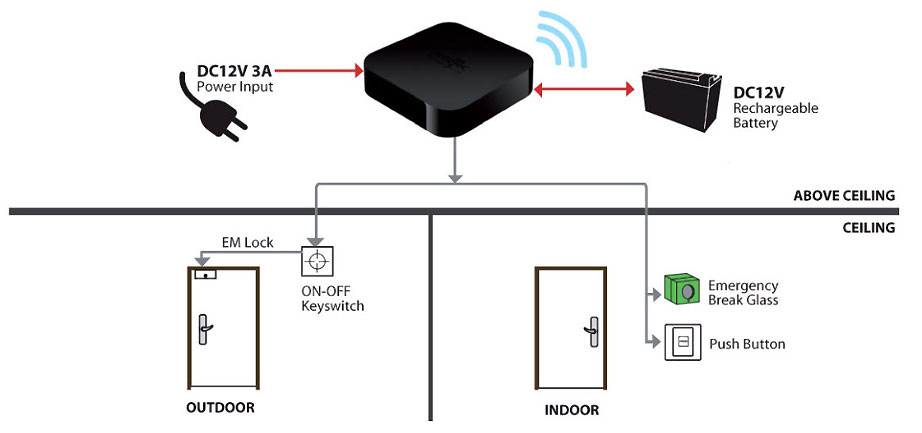
TimeTec Access Hub and its components
Unlike conventional door access controllers, which are embedded with access rules and verification algorithm, TimeTec Access Hub only acts a door controller and does not contain any data within it. Therefore while in idle mode, the hub will energize the electronic lock and secure the door as well as will unlock the door whenever it receives the unlock command sent from users’ smartphone via Bluetooth signal.

TimeTec Access Hub works as a main controller for receiving door unlock command from TimeTec Access Mobile App to control the door lock/unlock mechanism.

The Hub should be installed on top or next to the door in order to minimise the cabling required and and also ease users in unlocking the door. It is recommended to install it at the inner side of the premise to avoid vandalism.

As TimeTec Access Hub is a single door controller, you will need to survey the installation site and determine the amount of door prior to installation. To complete an installation for a single door, you will need:


1 set of 12VDC switching power supply as a main power source to the entire door lock system
1 set of electronic door lock (12VDC type EM lock, drop bolt, or compatible models), max 2 sets if it is a double leaf door
1 set of magnetic sensor to serve as a door sensor for monitoring the door’s action and provide status feedback to TimeTec Access Hub. The door status includes Normal Open, Force Opened, Door Left Opened, which will be uploaded into TimeTec Access to alert the administrators during break-ins
1 unit of emergency break glass as circuit breaker to deactivate the electronic door lock in case of an emergency
1 unit of 12VDC rechargeable backup battery to keep the door lock system in operation during a power failure. Note: include more batteries to serve a longer standby time
Optional Components :
  Push release button. Exclude this if you want to only allow authorised users to access the door
  Override key switch for overriding of the entire door lock system. Install the override key switch as a circuit breaker to deactivate the electronic door lock. Make sure that you secure the override key switch from any unauthorised individuals


As TimeTec Access Hub connects with TimeTec Access server to upload door status (door access records are uploaded from individual user’s mobile app), please ensure that the installation has an active connection to the Internet and WiFi router.
It is also important that the controller is installed according to the manufacturer’s specified environmental conditions, such as:

• Temperature
• Humidity
• Dust and other air contaminations
• Vibration
• Electromagnetic interference


Cables
Cables carry different signals, it could be data, communication, alarm or power. Inspections that need to be done include:

Visual inspections to make sure cables comply with the specifications
Ensure that no joints are made outside of junction boxes and that unapproved connection techniques are not used
Check for damage to the cores of the wiring and confirm that there is no missing insulation or that it is stripped back too far
No points in the wiring are to be stressed
Prove the consistency of the color codes
Ensure that the segregation of cabling from other cabling in the building is correct
Check for suppression being applied
Check cables within containments and that conduit is grounded
Verify the wiring routes are to the plans and follow the claimed routes
Ensure that the ambients of temperature that the cable is routed through cannot interfere with the performance of the wiring


Power Supplies
Failure of the power supply or the cabling to it can cause a total closedown of the system unless standby batteries are provided. For power supplies, please check the following:

The mains supply to the power supply should be correctly fused and be visually and electrically tested
Supplies to the access control system should be proved to be identified at their source
The power supply should have the efficiency of the earthing confirmed
Make sure that a UPS is in the location where maintenance can be easily carried out and that they are in a ventilated area, and installed in a location that’s secure from tampering


Signaling equipment
This part of the equipment testing involves us with the signaling that may be local within the protected areas or to a remote monitoring point or central station.

Local signaling should prove that any warning device or visual monitoring equipment receives the correct response in according with the transmission of a signal from the access control system
Any other security or building system or service integrated with the access control system should be verified as receiving an appropriate transmission
Door call units used with intercoms should be tested for audible and visual receipt at all appropriate points
A check should be made with the remote monitoring point or central station that the message that is to be generated is received


Communication equipment and software
This can form the final part of the equipment test schedule before the readings for the power circuits are logged.

All data must be checked for correct entry
All alarms must be correctly displayed
All access levels with the times of access allowed must be verified
Operator levels are to be defined
Events must be shown exactly as they occur and as specified
All automatic systems feature as specified
03.
TimeTec Access Account Setup


Go online and register a login account at TimeTec Access website. Sign in as a System Admin via web browser and start configuring the system. You will need to perform the steps as described below:

STEP 1 - Activate and configure the TimeTec Access Hubs and doors individually.
STEP 2 - Create the user accounts and login credentials. The system will then send invitation emails to the users and guide them in downloading and logging into TimeTec Access Mobile App.
STEP 3 - Create access time to restrict the users’ access. You can also configure a 24 hours access time as default for all users in accessing the doors.
STEP 4 - Create access group to assign users and the accessible doors, together with the access time.

NOTE: There are no physical or biological credentials being used within TimeTec Access Hub as only the Mobile App serves as the access controller and credential. Additionally, the Mobile App is embedded with the algorithm that determines the user’s accessibility. In other words, the Mobile App downloads the rules from TimeTec Access cloud server in order to confirm the user’s accessibility on the doors based on the smartphone’s date and time. Therefore, when the Admins make any changes in TimeTec Access cloud server, the Mobile App will receive the changes on the go. What’s more, as long as there is a WiFi connection, TimeTec Access Hub can be configured and linked towards TimeTec Access cloud server within the Mobile App. If there is no Internet connection, fret not as the system can still operate in Offline Mode but is unable to report the door status into the server.
0.4
System Handover - Tests required at the commissioning stage


At this point, the installer will be at the stage of handing over the electronic access control system to the client. In addition to presenting all of the documents in a professional manner, the customer must be briefed on the need for scheduled servicing and maintenance. The client must be instructed and advised that they must accept a measure of responsibility for the system to be used in the correct manner. To this end, the customer must be furnished with all documents related to essential components, drawings and a record for the installation. These documents must have all necessary operating manuals and instructions with diagrams of the site and parameter protection.

Documentations that need to t be prepared and as a minimum should include the following information.


General
Name, address and telephone number of the controlled premises
Name, address and telephone number of the customer
Location and classification of each access point and the type of location of each controller and its associated hardware
The type and location of power supplies
Details of those access points which the customer has the facility to isolate
The type and location of any warning device
Details and settings of any preset or adjustable controls incorporated into the system
Any documentation relating to equipment
The number of keys, codes token etc to the system provided to the client


Commissioning Data, confirm:
Correct termination of wiring
Voltage and resistance at all appropriate points of the system
Correct alignment and operation of access point hardware and of release and closure mechanisms at each access point
Correct operation of each reader
Release time for each order
Door held open signal, if specified
Verification of access levels
Function of system when mains disconnected
Following the completion of the handover, which should include the signing of contracts by both parties, the installer can confirm the need for maintenance and service and the schedule it is to follow.